Monday, November 22, 2010
Kitchen/Dining Room
This is looking into the galley kitchen. The cabinets are Crosley steel cabinets, the type your mother or grandmother couldn't wait to get rid of. The fridge is a 1932 GE (the first year the compressor was placed underneath). The countertops are linoleum that I fabricated on site. The window above the sink opens and I'm thinking about puttin a compost bin right underneath it.
The counter is curvey to match the cabinets. In the corner is a lazy suzan.

Here it is open.

The fridge was from a summer cabin and didn't seem to have had much use. A giant 5 cubic foot capacity. Will make it hard to engage in conspicuous consumption. White wine has to lay on it's side.

There's a little floating counter between the dining and kitchen. I wanted something just high enough so that people sitting at the table couldn't see the dirty bowls and utensils used to prepare the meal.

There are two more leaves and three more chairs that go with this set, but we won't be using them most of the time. The dining area was designed so that everybody gets a view from the table.

This upper kitchen cabinet opens towards the dining table for napkins, salt & pepper, and other things that might be needed while dining.

Master bedroom completed
We finally got a matress and can stay in the house. Yeah.

Here's another picture of the gorgeous marble remnant for the nightstand. I still haven't taken a picture that does it justice.

All the doors are in and the hardware installed. The plates and knobs are recycled. The "innerds" are new.

The Hydronic Heat
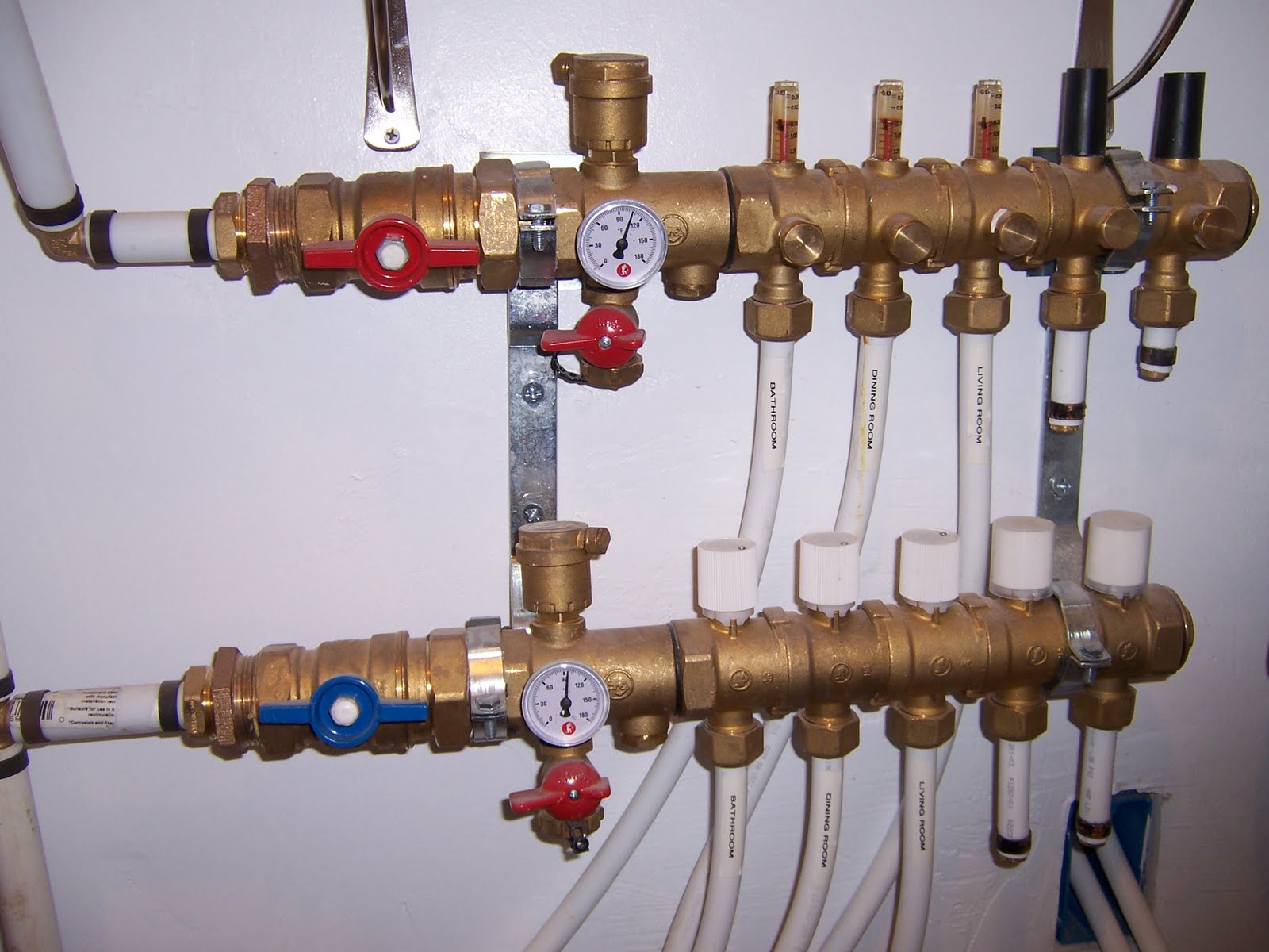
Here's the entire hydronic system.

Behind the recycled doors are the demand hot water heater and the potable water manifold. Cold water comes up through a pressure regulator and is distributed to the various fixtures. Some continues up to the demand hot water heater and then back down to the hot side of the manifold and out to the fixtures. What isn't shown is that the pipes to and from the demand hot water heater have Ts in them that allow hot water to be circulated to the hydronic system. Those pipes come out of the wall right in the middle of the picture with hot on the bottom and "cold" (return from the heat exchanger) on top.

Here's the guts of the system. When the thermostat demands heat, both pumps are activated. The brown pump in the lower center of the picture creates a demand on the demand hot water heater and 140 degree water is pumped in to the heat exchanger at the top center of the photo. The red pump on the right pumps water through the heat exchanger and that water is sent to the hot manifold, circulated though the floor, returns to the cold manifold, and then back to the heat exchanger.
On the wall above the brown pump and to the left of the heat exchanger is the controls for the whole house Energy Recovery Ventalation system. The ERV is on a timer that runs it several hours per day, or I can use a manual override. It is also connected with the ducting from the zero clearance fireplace. If I want the entire house to be the same temperature (not usually necessary), I can turn the ERV on manually. It actually is most useful in the summer, when upstairs temperatures can get to 80 degrees. The ERV can mix the cooler downstairs air with the upstairs air and keep things in the mid 70s when outside temps go above 90. 

Because the red "floor" pump on the left flows 30% more water than the brown "heater" pump on the lower right, the 140 degree water from the demand hot water heater only creates 110 degree floor water through the heat exchanger. In the picture, the water has been circulating for some time, and it is going out at 110 and returning through the slab at 90 degrees. That doesn't mean that the slab is 90 degrees. Heating the 90 degree water back to 140 in the demand heater only uses 1/3 of the demand heater's capacity, so there's plenty of capacity left for the washing machine, shower, etc., if that is used when the floor is heating.
I was surprised to find out that a demand for hot water at any of the household fixtures reduces the efficiency of the brown pump to the point where it barely sends warm water though (it effectively increases the "head" on the pump). What that means is that household fixtures have priority. If you're in the shower and the heat comes on, you won't notice. Basically, the hydronic heat won't effectively be on until the shower is finished. Not a big deal because my house temps only raise and lower about a degree per hour.
The manifold has control valves for the flow through each of the three 250' circuit loops, plus the manifold valves, the pump valves, and the pumps themselves can be adjusted for proper heat exchange and distribution. There were enough variables in the system such that I could fine tune it without any additional complex zone valves, bypass valves, etc. The system is very simple. (1/4/14 note: it has now been more than 3 years without an adjustment or any maintenance).
There is an expansion tank. The pex tubes coming through the wall run up into the attic. It's a project that I may or may not complete. So far, I'm happy with what I have, but the next picture explains the possible future use of this pex. Plus, I have to get the system strapped in better. I just pieced it together sufficient to get my certificate of occupancy.

In the attic is a water to air heat exchanger that can be connected to the pex tubing at the manifold. When the heat and the ERV are on at the same time, I can send 110 degree water up to the heat exchanger and then distribute warm air thoughout the house via the ERV ducting. In a similar manner, if it gets hot during the summer, I can send slab temperature water (65-68 degrees) though the heat exchanger and distribute cooler air through the house. The slab will gain some heat during a hot day, but it would distribute it overnight to the house. Haven't seen the need for the system yet. (1/4/14 note: Still haven't needed the system, although with climate change it might be nice to take late summer attic heat and store it in the slab).

The Stove
Here's the wood/electric stove in the kitchen. It's late 30's to early 40's vintage, when electrification was coming to rural Washington, but people weren't about to trust cooking and heating to new-fangled electricity. The stove is a Monarch, once famous for their woodstoves, now long out of business. The oven is both wood and electric. We built a nice fire to pre-heat the oven, put a chicken in to roast, and if the fire gets too low, the electricity comes on.


You can add fuel through the burners, or if you want to put in some bigger firewood, it has a special top that allows most of the top to lift. It also has a built-in timer on the backsplash. I found matching salt and pepper shakers for the warming shelf.

Because it is probably an electric conversion of a wood stove, the controls are on the side. They aren't marked as to which knob controls which burner, so it can be a little confusing at first.

The hood fan is a modern stainless with the actual fan in the attic where it can't be heard. Because of the tight construction, it is possible to backdraft the stove if it's not warmed up yet and the fan is turned on high. It has a dedicated cold air feed on the back side that comes from outdoors, but even that isn't enough. If you go back to the first picture, you'll see that the exterior door has a "speakeasy" in it (you can see that it is open). By opening the speakeasy, there is no backdrafting of the stove with the hood fan on and the dryer running. Still, it requires a little thought before lighting the woodstove.

![]()